2023-12-06
USB PD coding
I want to use USB Power Delivery (USB-PD) to power my stuff. There are dedicated chips and modules, supporting it, but it would be awesome if I could get it without any additional hardware. There are microcontrollers with USB-PD on board, but my plan is to go even lower and use my new favourite toy, the ch32v003. Last time I found a "secret temperature sensor" in it, this time I want to make it communicate via USB-PD. My goal for today is to sketch the basics of the protocol and to find out how to encode and decode the packets. The implementation on the chip will be done in a later post.
USB-PD basics
USB-PD is a protocol that is built on top of USB-C. It communicates via a dedicated wire, connected to the CC1 and CC2 pins of the USB-C connector. CC is used to detect the connection and to negotiate the power delivery. In the beginning, every USB-C device has a default role. It is either a source or a sink. For sources, the CC-Line has to be pulled up to 5V, sinks pull it down to GND. On connection, the source will turn on the supply of 5V via VBUS and supply a basic minimum current. The two can then negotiate other voltages and currents. Source and sink can also decide to switch roles, which is useful for laptops, power banks and other battery powered devices which can both be charged and provide power via the same connector.
I won't go too deep into detail about the high level protocol yet. I am going to focus on the physical layer of the protocol and how to implement it in software.
Physical layer
Before V3.0 there were two different physical layers for USB-PD. The legacy layer which used a BFSK signal, modulated onto the VBUS signal of USB-A connectors and the BMC-based layer which uses the dedicated CC lines. The legacy layer is now deprecated and only the CC communication is used in recent USB-PD standards.
I will talk about connections of the CC lines, driving the lines, signal levels and others in another post. This post is about the BMC encoding and decoding.
Packets are encoded as a bit stream and then encoded as a BMC signal. Decoding goes exactly the other way round. The BMC signal is sampled and the bit stream is decoded and the bit stream is then decoded into packets.
Packets
USB-PD is a packet based protocol. Every packet is transfered with the necessary overhead and in a standardised format. A packet is a sequence of the following components:
| preamble | SOP | message | CRC | EOP |
|---|---|---|---|---|
| 50 bits 010101... | 4 K-codes (4b5b) | header+data (4b5b) | 32 bits (4b5b) | 1 K-code (4b5b) |
There are also special hard reset and cable reset packets. They follow a different format, which I will not describe here.
Preamble
The preamble is a sequence of 50 alternating bits, starting with '0': '010101...'. It is used to synchronise the receiver.
4b5b encoding
The rest of the data is encoded as 4b5b code, which means that every 4 bits of data are encoded as 5 bits of signal. The encoding is done with a lookup table. The table also contains special codes (called K-codes) for the markers:
| hex | 5b |
|---|---|
| 0 | 11110 |
| 1 | 01001 |
| 2 | 10100 |
| 3 | 10101 |
| 4 | 01010 |
| 5 | 01011 |
| 6 | 01110 |
| 7 | 01111 |
| hex | 5b |
|---|---|
| 8 | 10010 |
| 9 | 10011 |
| a | 10110 |
| b | 10111 |
| c | 11010 |
| d | 11011 |
| e | 11100 |
| f | 11101 |
| ID | 5b |
|---|---|
| SYNC-1 | 11000 |
| SYNC-2 | 10001 |
| RST-1 | 00111 |
| RST-2 | 11001 |
| EOP | 01101 |
| SYNC3 | 00110 |
The remaining ten 5b-codes are reserved. Bytes and longer words are encoded in big endian. This means that the most significant nibble is encoded first.
SOP marker
Although there are other types of SOP* I will only describe the regular SOP marker. The SOP marker is a sequence of four K-Codes: SYNC-1, SYNC-1, SYNC-1, SYNC-2.
Message
There are three different types of messages: control messages, data messages and extended messages. Each message starts with the header word, which is a 16-bit word which describes the coming packet.
The header word is in the following format:
| bits | content |
|---|---|
| 15 | extended |
| 14-12 | # data objects |
| 11-9 | message id |
| 8 | port power role |
| 7-6 | spec revision |
| 5 | port data role |
| 4-0 | message type |
The format only applies to regular packets, marked by the SOP marker. The other types of SOP* markers have different formats. I will not describe all fields, that can be found in the specification. I might write about it in a later post.
Control messages
Control messages consist of only one 16-bit header. It is used for control purposes like discovering the identity of the other device or acknowledging a message. The number of data objects and the extended field are always '0' for control messages. The message id is used to identify the type of control message.
Data messages
Data messages are used to transfer data. They can be used to negotiate the power delivery, to transfer data or to send vendor specific messages. The extended field is '0' for data messages and the number of data objects describes the number of 32-bit data words that follow the header. The message id is used to identify the type of data message.
Extended messages
Extended messages are used to transfer data that doesn't fit into a single data message. They are for example used to transfer the identity of the device and the capabilities of the device. The extended field is '1' for extended messages. Extended messages have a 16-bit extended message header which follows the regular header. I will not describe the extended message header and the length of extended messages here, that might be a topic for another post.
CRC
The CRC is a 32-bit checksum. It is calculated over the whole message, including the header and the data, but not the preamble, the SOP markers and the EOP marker. The calculation of the CRC is described in the specification.
EOP marker
The EOP marker is a single K-Code: EOP. It marks the end of the packet. After the EOP marker, the CC lines are not driven by the transmitter anymore, resulting in the idle state of the CC line.
BMC encoding
The resulting bit stream has to be encoded as a BMC signal. BMC stands for "biphase mark code" and is a line code with a fixed bit rate / symbol rate. Every bit starts with a transition (rising or falling). For a '0' bit, the signal stays at the same level for the whole symbol, for a '1' it changes the level in the middle of the symbol.

Transmission
To transmit the packet bit stream, a simple synchronous sampling is used. With a sampling rate of 600 Kbit/s, the bit stream is sent out with two samples per bit, according to the BMC coding. The current line level is used as the initial state. It changes once for a '0' and again in the next sample for a '1'.
BMC decoding
There are multiple approaches to decode the BMC signal. They differ in complexity and in the hardware requirements for the receiver. The measurements that are required for the decoding are the times between the transitions.
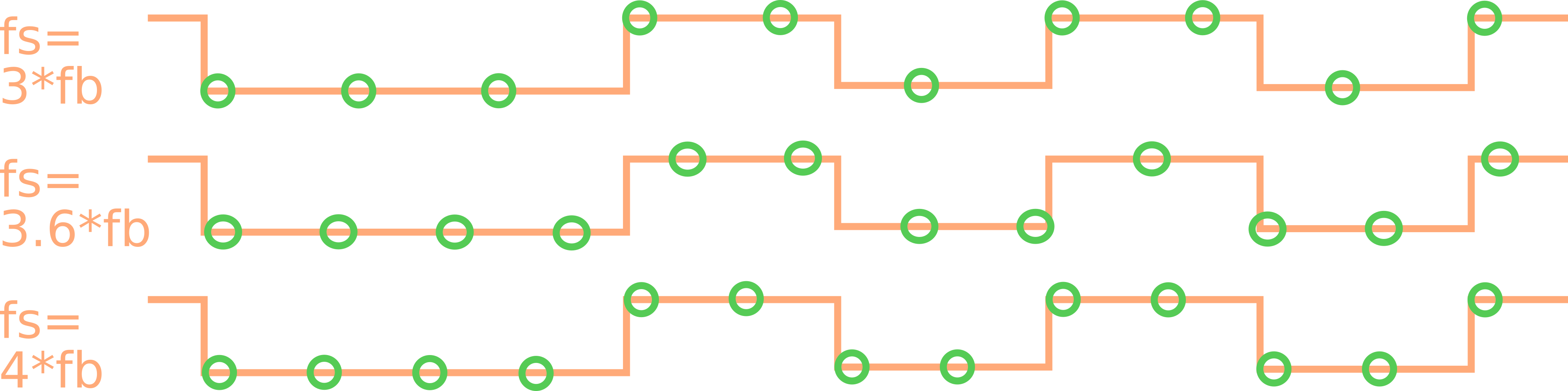
Synchronous sampling
For synchronous sampling, the input BMC signal needs to be oversampled with a fixed rate of at least 3 samples and at most 4 samples per bit. At this sampling rate, a '0' and the idle state can be detected unambiguously, because a '0' is always at the same level for either 3 or 4 samples. In the idle state, the line is high for 5 or more samples. A one has two transitions of each either 1 or 2 samples (also either 3 or 4 in sum).
Asynchronous sampling
Asynchronous sampling can be done by technically oversampling the signal at a much higher rate and using a counter to measure the time between the transitions. This can be done by using an interrupt to detect the transitions and an on-chip timer for the timing. This samples the signal at the clock rate of the timer, which can usually be much higher than the bit rate. The timer is reset on every transition and the time between the transitions is measured.

I decided for synchronous sampling, because I could wrap my head around it more easily. I might try the asynchronous approach in the future, but for now I will stick to the synchronous one. Also the synchronous approach is very easy to implement in hardware, either in HDL or manually with discrete logic. I just love FPGAs, you know?
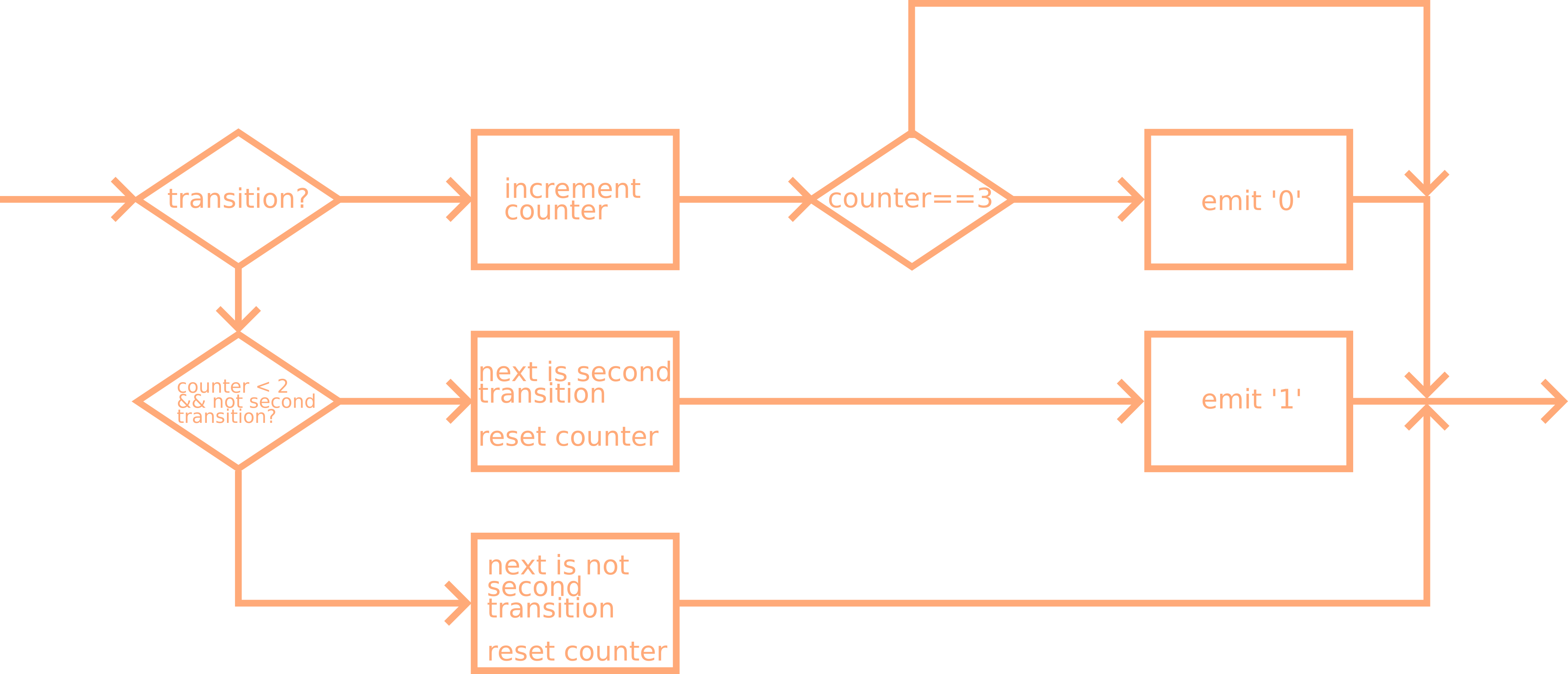
Decoder
I implemented the decoder sample wise. It is triggered with every sample and emmits decoded bits. I won't go into detail about the implementation, I will just provide the flow chart. Have a look at the repository, if you're interested.
BMC encoding
The encoding is done in a similar way. The bit stream is used as the input for the BCM encoder. The outputs the bmc signal with a sampling rate of two samples per bit. A '0' is encoded two samples of the same level, a '1' is encoded with a transition in the middle of the bit.
Collision detection
I didn't implement any collision detection yet. I might do that later, but for now I will just assume that there are no collisions.
Conclusion
These are my findings about encoding and decoding USB-PD packets. I will use this knowledge to implement a USB-PD stack on the ch32v003. The source code for the decoder and the encoder can be found in the github repo. I will write about that in a later post. I hope you found this interesting, if you have any questions or suggestions, please let me know!